Ka-band Scanning Polarimetric Cloud Radar (KaSPR)
|
|
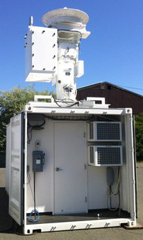
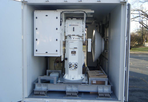
KASPR is a Ka-band (35-GHz) scanning polarimetric radar capable of polarimetric and Doppler spectra measurements. It can be configured to perform both vertically pointing (VPT) and scanning (PPI, RHI, HSRHI) sampling. KASPR is transportable (container-based) and can provide measurements in a wide spectrum of cloud and precipitation conditions from coastal fog to winter storms. The facility is complementary to other airborne and surface-based community observing facilities and is suitable for both land and ship-based deployments.
Examples of KASPR observations can be found here:
Kumjian, M. R., Tobin, D. M., Oue, M., & Kollias, P. (2020). Microphysical Insights into Ice Pellet Formation Revealed by Fully Polarimetric Ka-Band Doppler Radar, Journal of Applied Meteorology and Climatology, 59(10), 1557-1580. Retrieved Nov 18, 2021, from https://journals.ametsoc.org/view/journals/apme/59/10/jamcD200054.xml
Oue, M., Kollias, P., Matrosov, S. Y., Battaglia, A., and Ryzhkov, A. V. (2021): Analysis of the microphysical properties of snowfall using scanning polarimetric and vertically pointing multi-frequency Doppler radars, Atmos. Meas. Tech., 14, 4893–4913, https://doi.org/10.5194/amt-14-4893-2021
Lamer, K., Oue, M., Battaglia, A., Roy, R. J., Cooper, K. B., Dhillon, R., and Kollias, P. (2021): Multifrequency radar observations of clouds and precipitation including the G-band, Atmos. Meas. Tech., 14, 3615–3629, https://doi.org/10.5194/amt-14-3615-2021
Key features of the KASPR system include:
• Liquid cooled RF unit resulting in excellent temperature stability and sealed RF unit.
• Dry air system to remove moisture from RF unit, antenna and pedestal.
• 100 W, high duty cycle Solid State Power Amplifier (SSPA).
• Conduction cooled, 2.2 kW peak power 5% duty cycle Extended Interaction Klystron Amplifier (EIKA).
• Low-loss latching circulator network with three receiver protectors to assure adequate receiver protection even with short circuit load on antenna port.
• Pulse-to-pulse switchable H and V-polarized transmit polarization.
• Dual-channel 16-bit digital receiver (Pentek 78661).
• Arbitrary waveform generator (ARB) capable of generating any user-defined waveform of up to 16K samples in length.
• Internal monitoring of transmit power, receiver gain and receiver noise figure stored with each data record.
• Two remote-control power distribution units (PDUs). One PDU is located in the shelter to control power to the pedestal, RF units, chillers and dehydrator; a second PDU is located in the RF unit to control power to all subsystems.
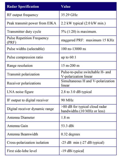
The KASPR technical specifications are shown in Table 1.
Examples of KASPR observations can be found here:
Kumjian, M. R., Tobin, D. M., Oue, M., & Kollias, P. (2020). Microphysical Insights into Ice Pellet Formation Revealed by Fully Polarimetric Ka-Band Doppler Radar, Journal of Applied Meteorology and Climatology, 59(10), 1557-1580. Retrieved Nov 18, 2021, from https://journals.ametsoc.org/view/journals/apme/59/10/jamcD200054.xml
Oue, M., Kollias, P., Matrosov, S. Y., Battaglia, A., and Ryzhkov, A. V. (2021): Analysis of the microphysical properties of snowfall using scanning polarimetric and vertically pointing multi-frequency Doppler radars, Atmos. Meas. Tech., 14, 4893–4913, https://doi.org/10.5194/amt-14-4893-2021
Lamer, K., Oue, M., Battaglia, A., Roy, R. J., Cooper, K. B., Dhillon, R., and Kollias, P. (2021): Multifrequency radar observations of clouds and precipitation including the G-band, Atmos. Meas. Tech., 14, 3615–3629, https://doi.org/10.5194/amt-14-3615-2021
Key features of the KASPR system include:
• Liquid cooled RF unit resulting in excellent temperature stability and sealed RF unit.
• Dry air system to remove moisture from RF unit, antenna and pedestal.
• 100 W, high duty cycle Solid State Power Amplifier (SSPA).
• Conduction cooled, 2.2 kW peak power 5% duty cycle Extended Interaction Klystron Amplifier (EIKA).
• Low-loss latching circulator network with three receiver protectors to assure adequate receiver protection even with short circuit load on antenna port.
• Pulse-to-pulse switchable H and V-polarized transmit polarization.
• Dual-channel 16-bit digital receiver (Pentek 78661).
• Arbitrary waveform generator (ARB) capable of generating any user-defined waveform of up to 16K samples in length.
• Internal monitoring of transmit power, receiver gain and receiver noise figure stored with each data record.
• Two remote-control power distribution units (PDUs). One PDU is located in the shelter to control power to the pedestal, RF units, chillers and dehydrator; a second PDU is located in the RF unit to control power to all subsystems.
The KASPR technical specifications are shown in Table 1.
Available Operating Modes:
The following operating modes are available in KASPR.
1. Standard pulse pair
2. Staggered PRI pulse-pair
3. Polarimetric pulse-pair
4. Standard FFT mode
5. Polarimetric FFT mode
Polarimetric data products that will be available from KASPR include the following: reflectivity, mean velocity, spectral width, LDR, ZDR, differential phase, specific differential phase, co-polarized correlation coefficient, SNR. Example PPI data gathered with a fully-polarimetric Ka-band radar are shown in the following figures. This data was derived from a polarimetric pulse-pair sequence in which the transmit polarization pattern was: H, H, V, V, H with a non-uniform pulse-repetition interval (PRI).
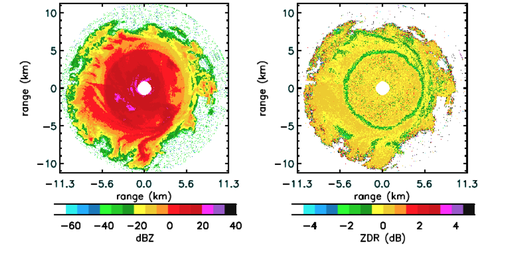
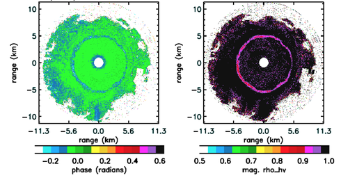
PPI scans of Ka-band reflectivity, ZDR, differential phase and co-polar correlation coefficient in stratiform rain showing enhanced ZDR, phi_dp, and rho_hv in the melting band. Elevation angle: 25 degrees.
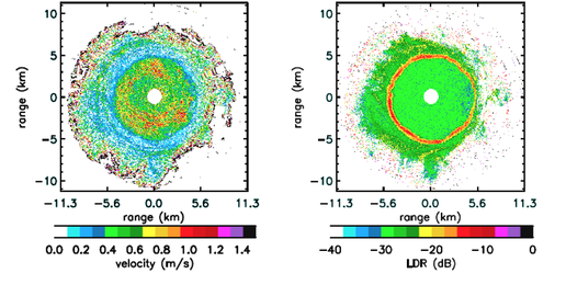
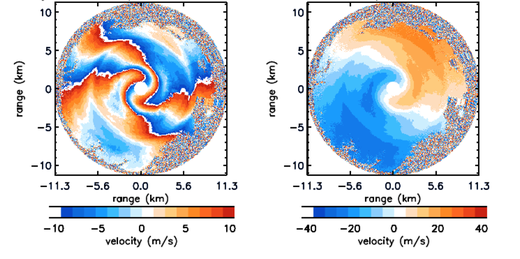
PPI scans of Ka-band spectral width, LDR, mean velocity derived from standard pulse pair (left) and dual-PRI pulse pair (right). The dual-pri velocity estimator provides a four-fold increase in un-ambiguous Doppler interval.
System Software
The system software for the KASPR is designed to take full advantage of multi-processor PCs with the processing load distributed equally among all processors. The software performs a variety of data processing functions, including pulse compression, clutter filtering, continuously updated noise estimation, power spectra computation, (FFT) processing, spectral moment estimation (pulse pair or moment estimation from Doppler spectra) and calibrated dBZ computation. Data files are stored in a custom binary format. The main file header describes the setting of the radar. Within the data file, each processed data block has a block header containing information such as antenna azimuth and elevation; transmit power, receiver noise powers, temperatures of key components, etc. Separate data files are stored for raw I/Q data, power spectra, and spectra moments (dBZ, velocity and velocity standard deviation). Recording of each of these data file types can be turned on/off. For example, when scanning rapidly, it is normal to only record spectral moments to minimize the stored data volume.
The system software for the KASPR is designed to take full advantage of multi-processor PCs with the processing load distributed equally among all processors. The software performs a variety of data processing functions, including pulse compression, clutter filtering, continuously updated noise estimation, power spectra computation, (FFT) processing, spectral moment estimation (pulse pair or moment estimation from Doppler spectra) and calibrated dBZ computation. Data files are stored in a custom binary format. The main file header describes the setting of the radar. Within the data file, each processed data block has a block header containing information such as antenna azimuth and elevation; transmit power, receiver noise powers, temperatures of key components, etc. Separate data files are stored for raw I/Q data, power spectra, and spectra moments (dBZ, velocity and velocity standard deviation). Recording of each of these data file types can be turned on/off. For example, when scanning rapidly, it is normal to only record spectral moments to minimize the stored data volume.